
After building the LilyPad Arduino vest, I got to thinking that it didn’t have much purpose for students beyond demonstration and inspiration. I wanted a project that students could actually use in some way, to learn and practice their skills in circuitry and coding. Brainstorming with colleagues is always helpful in working out viable ideas and foreseeable problems. I usually seek out people who can contribute to the how-to part of a project, as well as people who will pick apart my idea and reveal the problems I might encounter. Thanks to some helpful ugly doll discussions, I decided to make a complete doll as a prototype and as a tool for learning and practicing programming in C.
The inspiration for this doll came from Leah Buechley’s project described in her book Sew Electric. The materials needed are about a half yard of fleece (This will really make two dolls), regular sewing thread, conductive sewing thread, and sewing needles. For the electronic components you will need a LilyPad Arduino, a LilyPad power supply, one LED, one speaker, one accelerometer, and one light sensor. All of the components were either made by LilyPad or were compatible with LilyPad. (Although I love the clean look and low profile of the LilyPad products I have found that compatible products can be purchased on Ebay for about 25% of the cost.)
The shape of the doll was drawn on paper, showing both the front and the back. The placement of these components was sketched in. Keeping in mind that if positive and negative traces cross it will create a short circuit, the path of the traces was sketched using a red marker for positive and a black marker for negative. The positive and negative pins on the LilyPad had to be connected to the positive and negative pins on the power supply. The positive pins on each of the components had to be connected to the LilyPad as follows:
1. Outputs (the LED and speaker) were sewn to digital PWM pins on the LilyPad.
2. Inputs (accelerometer and light sensor) were sewn to analog pins.
The negative pins on each of the components had to be connected to the negative pin on either the LilyPad or the power supply (or to any part of a negative trace) without crossing any of the positive traces. If crossing was unavoidable, insulation could be added by sewing a piece of fleece fabric between the two traces at the crossing point.
I wondered if an on/off switch could be added to the light sensor and the accelerometer to disable them when desired. So I tested this before sewing by attaching them with alligator clips. I later decided that since different programs could be uploaded to the LilyPad (some including those components and others not) it really didn’t matter. If I didn’t want them to be active, I could just use a program that did not access them.
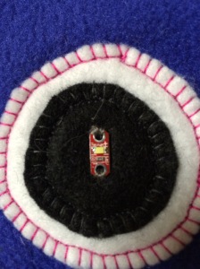
LilyPad Arduino – isn’t it beautiful? 


The circuitry was sketched on paper to act as a guide for sewing the traces with the conductive thread. (Lesson learned in the LilyPad Arduino Vest) The pink lines indicate the positive traces.
The materials used for the doll included fleece fabric, sewing thread, and conductive thread.
LilyPad Arduino and Power Supply – The power supply (battery holder) has one positive pin and three negative pins. It also has an on/off switch.
LED sewn on with conductive thread. Note that the positive pin is indicated with a +.

Speaker (Also referred to as a buzzer) Note that the positive pin is indicated with a +.

Accelerometer – Note that there are pins for X, Y, and Z axes. Note that the positive pin is indicated with a + and negative indicated by a -.

Light Sensor – Note that the positive pin is indicated with a + and negative indicated by a -.
Here you can see a video of the LilyPad Arduino Ugly Doll in action.

I left the doll sewn on only one side so that it can be opened like a book to reveal the traces. After constructing the doll and making sure all the components worked, I sewed an extra piece of doll shaped fleece on the inside, kind of like a page in a book. This serves to prevent short circuits when the doll is “closed.”
My next step is to learn how to write the code for the two inputs (light sensor and accelerometer). Stay tuned.


